


Program 'SPECTRON OPS' helps reduce the time necessary for designing fire security systems in AutoCAD. Equipment produced by SPECTRON company are used in the program.
Customer: Spectron (http://spectron-ops.ru/)
Program 'SPECTRON OPS' helps reduce the time necessary for designing fire security systems in AutoCAD. Equipment produced by SPECTRON company are used in the program.
Customer: Spectron (http://spectron-ops.ru/)
Program purposes:
The program 'SPECTRON OPS' helps reduce the time necessary for designing fire security systems in AutoCAD. Equipment produced by SPECTRON company is used in the program.
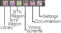
The program has its own toolbar with buttons, which appear after downloading *.DLL file by NETLOAD command.

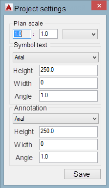
First, the user must set the project's parameters, including drawing scale.

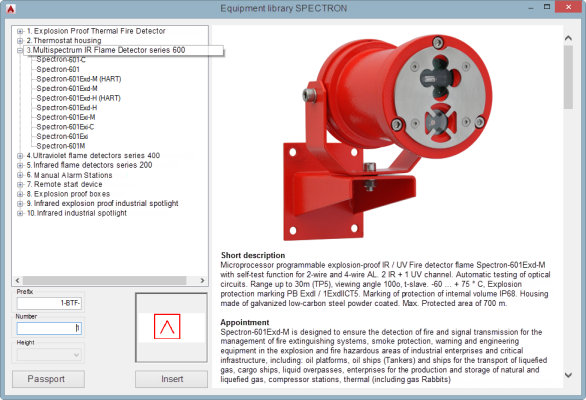
Secondly, the user has to insert DWG blocks (symbols) on the building plan. The Equipment Library window is opened by clicking on the "Library" button.

The window includes the equipment list on the left side and a brief description and photo on the right, which appears after choosing a specific model.
A brief description helps the user to choose an appropriate model. If a full description is needed, click the “Passport” button. Under description, users can see a preview of DWG blocks, which will be inserted on the drawing.
After blocks are inserted, each block receives an index number and unique handle. Users can set prefixes.
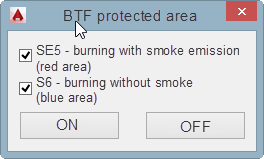
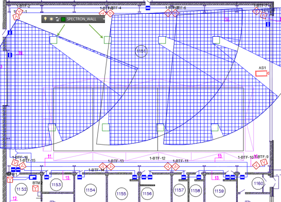
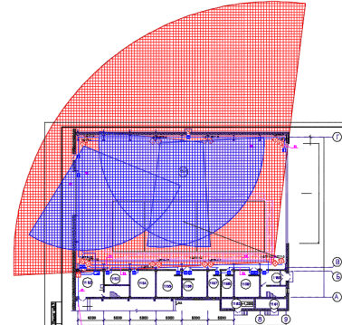
There's the opportunity to show areas for flame and thermal detectors where its influence extends. These are designated as a protected area. Use the 'BTF region' button:

In the window, the user has to choose the conditions:
• SE5 – burning with smoke emission (red area)
• S6 - burning without smoke (blue area)


It is very important that the user mark or draw barrieres that interrupt the signal from continuing.
To draw barriers, open the SPECTRON_WALL layer in AutoCAD and draw obstructions using basic AutoCAD commands (line, polyline, etc.) or insert prepared grapohics in the SPECTRON_WALL layer.

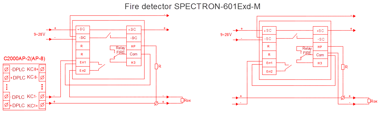
Wiring diagrams are drawn only for selected equipment using the "Wiring Scheme" button.
AFfer clicking the button, the mouse cursor becomes a small square for selecting DWG symbols on the drawing or selecting regions. Press Enter, move the cursor to an empty place on the drawing, and wiring diagrams will be set automatically for selected equipment.

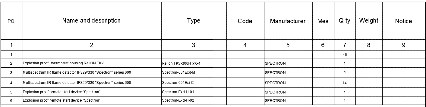
The same method is used for creating BOM (specifications). After clicking the 'Documentation' button, the cursor becomes a small square for selecting DWG symbols on the drawing or selecting regions. Press Enter, click an empty place on the drawing and specifications will be set automatically for selected equipment.
